Casio VZ-1 algorithms
2024-08-03
Following on to my last post, where I found out that the official documentation of the Casio VZ-1 keyboard synthesizer from 1988 contains vague and incomplete information about how the machine works, I want to write down what I wish the manual would have said.
Recap
Casio does a very poor job of explaining the synthesis engine of the VZ-1. They never actually say that it does phase modulation but they do not clearly explain that it does wave shaping either. On top of that the user interface causes confusion by things like:
- Letting you change the pitch of an operator in the UI that is in reality locked to 0Hz.
- Having hidden "exciter" operators that are disabled according to the UI but that control pitch and wave shape of another (0Hz) operator.
- Having operators show as disabled in the UI when in fact they are acting as wave shapers and hence letting through signals that the UI suggests should get blocked.
- Etc.
I am not alone in interpreting Casio's information to mean that the VZ-1 uses phase modulation. In an October 1989 Music Technology review of the related Casio VZ-8M, for example, the reviewer calles the synthesis engine a
digital synthesis system which, in conceptual terms, could loosely be considered as a user-configurable version of Yamaha's FM synthesis
Similarly Sound on Sound wrote in February 1990:
the simple two module stacks are like two operator pairs in FM, the parallels are like parallel sets of operators
The 1988 book "POWER PLAY VZ!" by De Furia and Scacciaferro, which is a kind of third party manual for the VZ series, says on page 57:
The output of M1 phase modulates the DCO in M2
And I could go on. Thanks to acreil we now know there is no phase modulation anywhere in the VZ-1. So, how do the algorithms really work?
Single line
The VZ-1 voice has 8 operators ("modules") grouped in pairs as 4 "lines". Lines can sound in parallel or they can be cascaded. We start with considering a single line.
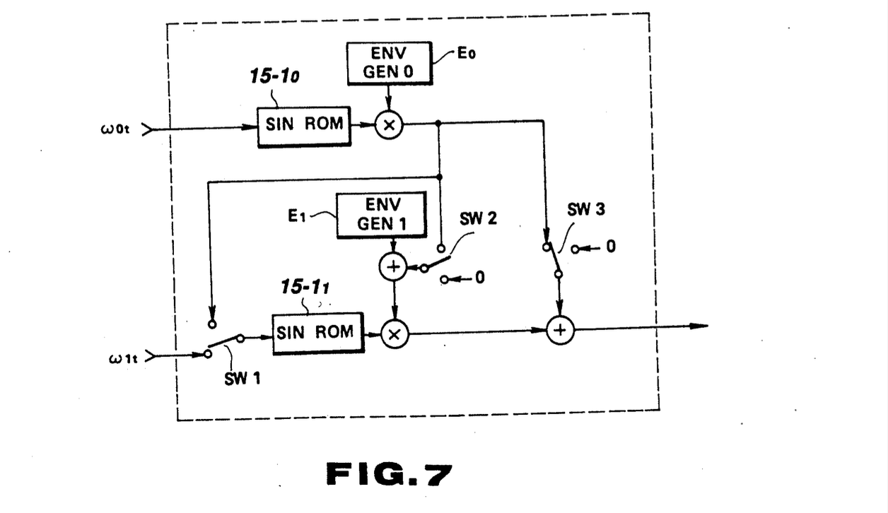 Image source: US patent 5040448A
We will consider Line A which consists of operators M1 and M2. Note that the picture above is 0-indexed so e.g. ω0t is the phase of operator M1.
MIX mode
Formula: M2 + M1.
In the picture this means SW1 down, SW2 down, SW3 left. The signals of M1 and M2 are summed together. M1 and M2 have independent amplitude envelopes, wave shapes and pitches.
RING mode
Formula: M2 * M1. Note that the synth UI more correctly states M2 + M1 * M2 but that will get too verbose later on.
This is SW1 down, SW2 up, SW3 right. The product of M1 and M2 is summed with the dry signal of M2. The product signal amplitude is modulated by envelope 1 and the dry signal of M2 is modulated by envelope 2. M1 and M2 have independent wave shapes and pitches.
PHASE mode
Formula: M2(M1).
This is SW1 up, SW2 down, SW3 right. Because SW1 is up, ω1t (the phase of M2) is ignored. The output is M1 wave-shaped (distorted) by M2. Envelope 1 controls the amplitude before the wave shaper and envelope 2 controls the amplitude after the wave shaper (pre- and post-gain). The pitch of M1 determines the overall pitch and the pitch of M2 is ignored. The shape of M1 determines the wave shape of the input signal and the shape of M2 determines the wave shaping curve, i.e. the kind of distortion that is applied to M1.
If you disable M2 there is no sound. If you disable M1 it secretly stays enabled as the exciter of M2. This is needed because M2 oscillates at 0Hz so without excitation it cannot make sound. All that disabling M1 really does is to override envelope 1 with a constant value (the excitation amplitude).
Two lines
So what happens if you use an "external phase" cascade of one line into another? Below we assume Line B has external phase on, so Line A cascades into Line B, and Line C has external phase off, so there is no third stage. The image below is again 0-indexed.
 Image source: US patent 5040448A
Line A MIX, Line B MIX: M3 plus the wave-shaped sum of M1 and M2
- Formula:
M4(M2 + M1) + M3 - SW1 is down, SW2 is down, SW3 is left, SW4 is left, SW 5 is down, SW6 is down, SW7 is left, SW8 is right.
- The output is the sum of M3 and M4. M3 is an independent operator with its own pitch, wave shape and amplitude envelope.
- M4 is a wave shaper with Line A as its input. If M2 is disabled in the UI it secretly remains enabled as the exciter for M4. Its signal still gets routed through M4 at a fixed volume. Even though M2 is disabled, changing the pitch and wave shape of M2 has an audible effect on the signal coming out of M4.
- If you leave M2 enabled but set its envelope depth to 0 then the same thing happens as when you disable M2: it acts as an exciter for M4.
- If M4 is the only operator that is enabled then envelope 4 controls the amplitude of the resulting sound. The wave shape of M4 determines the wave shaping curve of the resulting sound. The input wave shape and pitch are controlled by M2. If you set M2 and M4 to a sine wave you will not get a pure sine wave out of M4 because M2 as an exciter drives M4 lightly outside the linear region.
Line A RING, Line B MIX: M3 plus the wave-shaped ring modulation of M1 and M2
- Formula:
M4(M2 * M1) + M3 - SW1 is down, SW2 is up, SW3 is right, SW4 is left, SW 5 is down, SW6 is down, SW7 is left, SW8 is right.
- The output is the sum of M3 and M4. M3 is an independent operator with its own pitch, wave shape and amplitude envelope.
- M4 is a wave shaper with Line A as its input. If you disable M2 in the UI it remains active as an exciter for M4 (see above).
Line A PHASE, Line B MIX: M3 plus doubly wave-shaped M1
- Formula:
M4(M2(M1)) + M3 - SW1 is up, SW2 is down, SW3 is right, SW4 is left, SW 5 is down, SW6 is down, SW7 is left, SW8 is right.
- The output is the sum of M3 and M4. M3 is an independent operator with its own pitch, wave shape and amplitude envelope.
- M4 is a wave shaper with Line A as its input. Recall that M2 is now also a wave shaper so this time it is not the exciter. Disabling M2 has no effect. M1 is the exciter for M4 and you cannot interrupt the signal flow from M1 through M2 to M4.
- The only effect of enabling M1 or M2 is that you get to use their respective amplitude envelopes. Because of the series arrangement of M2 and M4, the default envelopes for M1 and M2 result in a lot of wave shaping distortion.
Remaining two-line combinations
Recall that I have shortened the official notation for ring modulation from M2 + M1 * M2 to M2 * M1. In other words the dry signal (M2) in ring modulation is implied.
| Line A | Line B | M4 exciter | Formula | Description |
|---|---|---|---|---|
| MIX | RING | M2 | M4(M2 + M1) * M3 | M3 ring-modulated with the wave-shaped sum of M1 and M2 |
| RING | RING | M2 | M4(M2 * M1) * M3 | M3 ring-modulated with the wave-shaped ring modulation of M1 and M2 |
| PHASE | RING | M1 | M4(M2(M1)) * M3 | M3 ring-modulated with the doubly wave-shaped signal of M1 |
| MIX | PHASE | M3 | M4(M3 + M2 + M1) | wave-shaped sum of M1, M2 and M3 |
| RING | PHASE | M3 | M4(M3 + M2 * M1) | wave-shaped sum of M3 and the ring modulation of M1 and M2 |
| PHASE | PHASE | M3 | M4(M3 + M2(M1)) | wave-shaped sum of M3 and the wave-shaped signal of M1 |
Three and four line combinations
I won't spell these out; there are 27 3-line combinations and 81 4-line combinations. I am also doubtful how useful they will be because more and more operators will pass through multiple layers of wave shaping which is a form of distortion.
The exciter operator will be the lowest even operator in the cascade, unless any of the lines uses PHASE mode in which case the odd operator of the highest PHASE line is the exciter. Three and four-line cascades also introduce another unexpected behavior around excitation. Consider the three-line cascade with all lines set to MIX: M6(M4(M2 + M1) + M3) + M5. Because M4 acts as a conduit for the exciter M2, M4 can never truly be disabled. This explains the mystery I encountered previously. In other words the undocumented "always on" behavior of the exciter also applies to all "exciter conduit" wave-shapers after it, except the last wave shaper in the cascade.
Conclusion
Casio made such a confusing mess of things with the always-on exciters, the exciter conduits and the wave shapers whose frequencies can be edited in the UI but not in the engine. It is almost a case study in what goes wrong when you lie to the user about what goes on inside the machine. Lying is a harsh word to use but when "disable" does not mean disable then I don't know what else to call that.
It would have been very hard for the manual to explain all this so pragmatically I understand why it does not tell you what is really going on. The problem is in the design of the synthesis engine, not in the manual.
It looks like Casio came up with some interesting and distinctive synthesis ideas but then failed design this into an understandable system. It reportedly cost Yamaha 10 years and who knows how much money in R&D to turn their license of phase modulation synthesis ("FM", license acquired in 1973) into a usable product (the DX7 in 1983). And then there was still more room for improvement and simplification until they released the TX81Z in 1987 which is perhaps the final form of first-generation Yamaha FM. I doubt that Casio was able to spend that much time and money on developing the VZ-1.
I need a break from the VZ-1 now before I return to it to actually make sounds to use in my music, but I had fun learning all this obscure stuff about it.
Errata 2025-07-08
In the original version of this post I made a mistake in describing what happens when using "external phase" and having one or more lines in PHASE mode. I wrote that the exciter is in the lowest line that uses PHASE. It is the other way around, it is in the highest line that uses PHASE. I have corrected the table and the text in this post.