Modifying "rev B" CrowBX voice cards to use the AS3310
March 2020, by Jacob Vosmaer.
The idea of this hack is to take a working CrowBX rev B voice card and retrofit an AS3310 onto it. Maybe you want to match rev B voice cards with newer ones that use the AS3310, or with original OB-X voice cards that use the CEM3310.
This mod leaves as many parts of the non-3310 EG's in place as possible, to make it easier to revert the mod for whatever reason.
Bill of materials
Per voice card:
- 2x AS3310 IC
- 2x 680R resistor
- 2x 24K resistor
- 2x 1n capacitor
- 2x 22n capacitor
- 2x 47n capacitor (poly film)
The 47n capacitor and the 24K resistor control envelope timing.
The 1n capacitor is there to automatically create a trigger signal
when the gate goes up; the 3310 has a trigger input but the OB-X
only has a gate signal so the trigger must be derived from the gate.
The purpose of the 22n capacitor is not clear to me.
The 680R is a current limiting resistor for the negative rail, which
is internally regulated to -6.5V by a zener inside the 3310.
VCA
Remove:
- IC1, IC2, IC3, IC4
- C16, C18
- D6, D7, D10
- Q24, Q26, Q27, Q34
- R43, R44, R118, R120, R122, R126, R128, R146, R154, R159, R194
When removing R43 and R128 it may help to also cut R166, which is part of the
VCF envelope and which is not needed anymore if you install an
AS3310 on the VCF.
Connect:
- D6 top to R122 right
- D7 top to R118 bottom
- D10 left to R154 right
- R159 left to R44 top
- R44 bottom to R122 left (ground)
Use wire wrap wire.
Install:
- 47n capacitor on R128
- 24K resistor on R194
- jumper on R43
- 22n capacitor between top and right pin of Q24
- Bend out AS3310 pin 5 and 6
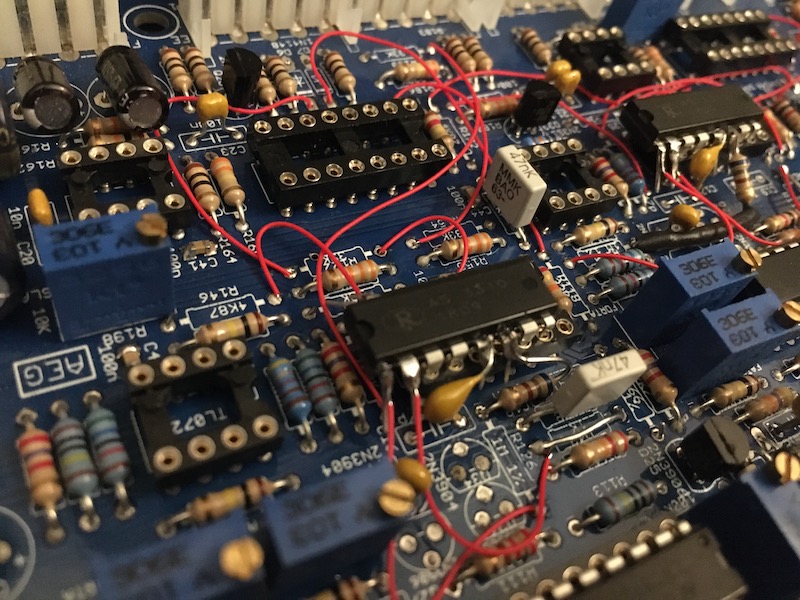
- Install AS3310 in socket of IC1 (TL074), with AS3310 pin 3 in socket pin 8
Note that the AS3310 is facing the wrong way, and it has its pins 1,
2, 15, 16 floating to the right of the socket. Pins 5 and 6 should
not be socketed.
Fly:
- AS3310 pin 1 to R128 (now cap) top or R126 top
- AS3310 pin 2 to R43 (now jumper) or C18 left
- AS3310 pin 15 to R146 left
Use wire wrap wire.
Special:
- 1n cap from C16 left to AS3310 pin 5
- 680R resistor from R126 bottom to AS3310 pin 6
Both of these have one component leg in the board, and one leg flying
to an AS3310 pin.
VCF
Remove:
- IC5, IC6, IC8, IC9
- C17, C19
- D8, D9, D11
- Q29, Q30, Q31, Q32
- R119, R121, R123, R125, R127, R170, R171, R172, R180, R185, R195
Connect:
- D8 bottom to R127 top
- D9 bottom to R125 left
- D11 left to R180 bottom
- R185 right to R121 top
- R121 bottom to R180 top (ground)
Use wire wrap wire.
Install:
- 47n capacitor on R171
- 24K resistor on R195
- jumper on R119
- 22n capacitor between top and right of Q30
- Bend out AS3310 pin 5 and 6
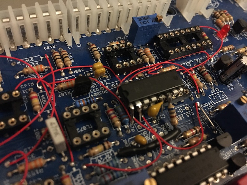
- Install AS3310 in socket of IC5 (TL074), with AS3310 pin 3 in socket pin 8
Note that the AS3310 is facing the wrong way, and it has its pins 1,
2, 15, 16 floating to the right of the socket. Pins 5 and 6 should
not be socketed.
Fly:
- AS3310 pin 1 to R170 right
- AS3310 pin 2 to R119 (now jumper) or C19 left
- AS3310 pin 15 to R172 bottom
Use wire wrap wire.
Special:
- 1n cap from C17 left to AS3310 pin 5
- 680R resistor from R170 left to AS3310 pin 6
Both of these have one component leg in the board, and one leg flying
to an AS3310 pin. Put insulation (heat shrink) around the 680R
resistor because it has to bridge a long distance.
Why does this work?
Here is a map of the AS3310 pins to the TL074 pins in this mod.
"Ax" refers to "pin x of the AS3310" and "Tx" means "pin x of the
TL074 socket".
| AS3310 pin | socket | description |
| A1 | hanging outside socket | 47n cap to ground via flying wire |
|---|
| A2 | hanging outside socket | envelope output via flying wire |
|---|
| A3 | T8 | unused, mechanical connection only |
|---|
| A4 | T9 | gate input |
|---|
| A5 | bent out | 1n cap to A4 |
|---|
| A6 | bent out | 680R to -15V |
|---|
| A7 | T12 | ground |
|---|
| A8 | T13 | 22n cap to ground |
|---|
| A9 | T2 | sustain input |
|---|
| A10 | T3 | 24K resistor to A2 |
|---|
| A11 | T4 | +15V |
|---|
| A12 | T5 | decay input |
|---|
| A13 | T6 | release input |
|---|
| A14 | T7 | ground |
|---|
| A15 | hanging outside socket | attack input via flying wire |
|---|
| A16 | hanging outside socket | unused |
|---|
If you look closely at the CrowBX schematics and the original OB-X
schematics then this should all add up.
Back